
Clamps
Product List
| Part Number | Bolt Ineraxys | Standard Clamping Forces | Hockey Puk Types | Bolt Lengths |
|---|---|---|---|---|
| CO54 | 54mm (2.00") | 5 KN (1,125 lbs.) | DO-200AA 19mm (A-Puk) | 70-110 mm |
| CO70D | 70mm (2.75") | 5 KN (1,125 lbs.) 9.8 KN (2,205 lbs.) 12 KN (2,700 lbs.) | DO-200AA 19mm (A-Puk) TO-200AB 25mm (E-Puk) | 70-180 mm |
| CO89D | 89mm (3.50") | 12 KN (2,700 lbs.) 14 KN (3,150 lbs.) 18 KN (4,050 lbs.) | TO-200AB 34mm (B-Puk) | 70-180 mm |
| C102A | 102mm (4.00") | 18 KN (4,050 lbs.) 22 KN (4,950 lbs.) 24 KN (5,400 lbs.) | DO-200AC 50mm (K-Puk) | *80-250 mm |
| C102B | 102mm (4.00") | 18 KN (4,050 lbs.) 22 KN (4,950 lbs.) 24 KN (5,400 lbs.) | DO-200AC 50mm (K-Puk) | *80-250 mm |
| K102B | 102mm (4.00") | 30 KN (6,750 lbs.) | DO-200AC 50mm (K-Puk) | 140-190 mm |
| K140B | 140mm (5.50") | 27 KN (6,075 lbs.) 45 KN (10,125 lbs.) | TA20 63 | 140-200 mm |
| C155A | 155mm (6.10") | 45 KN (10,125 lbs) 50 KN (11,250 lbs.) | B-44 75 mm (R-Puk) | *160-240 mm |
| SB Series** Box Clamps | 35.5mm x 35.5 mm (1.40") | 5 KN to 10 KN (1,125 lbs to 2,250 lbs) | DO-200 AA 19mm (A-Puk) TO-200 AB 25 mm (E-Puk) | NA |
| KX 94 Series** Box Clamps | 74mm x 60 mm (2.91"2.36") | Up to 17 KN (3,825 lbs) | TO-200 AB 34mm (B-Puk) | NA |
GENERAL INFORMATION
Clamps for Hockey Pucks
These two types of clamps have a preloaded cup shaped springs system which guarantees the perpendicularity of the clamping force even without ball joints. A washer on the spring guide indicate the achievement of the right force. In order to have a correct mounting, the following is recommended:
Technical Characteristics
The bars of clamps type CO70, CO89 and CO102 are made of high resistant steel.
The cup shaped springs are made of steel UNI 50CrV4. Upon request they can be made of stainless steel.
The screws and bolts are made of steel class 8.8.
All metal parts are galvanicaly treated in order to be corrosion proof.
Insulator Properties
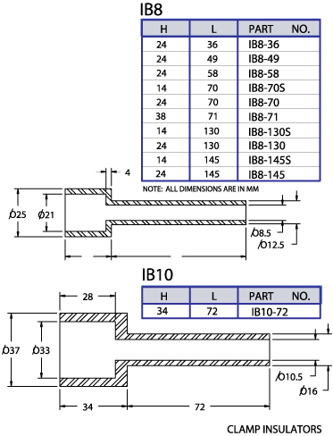
The insulators for the clamp are made of polyammide 6.6 with 50% glass fiber added. The have dielectric property of 85KV/mm. The thickness of the IB8 insulator is 1.7mm, the IB10 is 2.7mm working temperature of 105 C.
Clamping force conversion; 1 KN=225 LBS, 1 Kg=9.806N, 1 Kg=2.2 LBS.
Clamp Selection
The choice of the clamp suitable for each different application can be made
according to three main parameters:
a) Type of semiconductor (diameter and thickness)
b) Requested clamping force
c) Total thickness of heatsink
INSULATORS
MOUNTING DIRECTIONS
MOUNTING INSTRUCTIONS FOR CLAMPS
TYPE C070-C089
These two types of clamps have a preloaded cup shaped springs system which guarantees the perpendicularity of the clamping force even without ball joints. A washer on the spring guide indicate the achievement of the right force.
In order to have a correct mounting, the following is recommended:
- The two contact surfaces of semiconductor should be covered with a thin coating of an approved joint compound and then the possible surplus should be removed.
- Locate the semiconductor on one of the two heatsinks centrally by using the provided pin after having checked the polarity. Then the semiconductor should be rotated to spread the compound.
- Position the second heatsink on the semiconductor and located it centrally by using a second pin. Then slightly rotate the heatsink to spread the compound.
- Mount the clamp on the heatsinks by tightening alternately the bolts with a wrench up to the contact with the metal washer of the insulator checking the alignment of heatsinks semiconductor.
- Tighten alternately both bolts each time about 1/6 turn until the indicating washer turns free, then tighten both bolts once more about 1/10 turn.
MOUNTING INSTRUCTIONS FOR CLAMPS TYPE C102
This type of clamp has a preloading system consisting of two sets of springs, a ball joint which assures the perpendicularity of the load force and two tangs which indicate the achievement of loading force. An advantage of this kind of clamp is the reduced overall size in comparison with the other with central spring bolts.
In order to have a correct mounting, the following is recommended:
- The two contact surfaces of semiconductor should be covered with a thin coating of an approved joint compound and any surplus should be removed.
- Locate the semiconductor on one of the two heatsinks centrally by using the provided pin. The semiconductor should be rotated to spread the compound.
- Position the second heatsink on the semiconductor locate it centrally by using a second pin. Then slightly rotate the heatsink to spread the compound.
- Tighten the two bolts on the short threaded side.
- Position the ball joint on the back of the heatsink by using the proper split dowel pin.
- Mount the clamp on heatsinks semiconductor set by tightening alternately the nuts on the bolts up to the contact with metal washers of the insulator, taking care that the bar is parallel to the heatsink and the heatsinks semiconductor set is aligned and parallel.
- Tighten alternately the nuts about 1/8 turn each until the indicating tanks are free.
- Tighten both nuts once more about 1/12 turn.
MOUNTING INSTRUCTIONS FOR CLAMPS TYPE C155
This type of clamp uses the elasticity of bar material. The indicator of the load force
is a tang which is fixed on one side and free on the other.
The perpendicularly of the load force is guaranteed by a proper floating joint.
In order to have a correct mounting, the following is recommended:
- The two contact surfaces of semiconductor should be covered with a thin coating of an approved joint compound and then any surplus should be removed.
- Locate the semiconductor on one of the two heatsinks centrally by using provided pin after having checked the polarity. Then the semiconductor should be rotated to spread the compound.
- Position the second heatsink on the semiconductor and locate it centrally by using a second pin. Then slightly rotate the heatsink to spread the compound.
- Position on the back of the heatsink the floating joint by using the proper split dowel pin.
- Mount the clamp on the heat sink semiconductor set using two wrenches to tighten the nuts on the screws up to the contact with the metal washers of the insulator, taking care that the above set is aligned and parallel.
- Tighten alternately the nuts about 1/6 turn each until the indicating tangs are free.
- Tighten both nuts once more about 1/12 turn.
- In care of disassembly of the clamp for a possible replacement of the semiconductor, before loosening the nuts, flex the tank slightly outward to the point that it gets free from the bar.